ESP32 boards for the wall box: a smart socket with power metering and a dual TRIAC switch with and without neutral, KiCad and ESPHome files
Non-isolated ESP32-C3 boards that fit in a Ø60 wall box: a relay socket module that measures power with a BL0937, a two-channel TRIAC light switch, and a version of the switch without neutral that powers itself through the lamps. They connect to Home Assistant through ESPHome and have thermal lockouts. The KiCad projects, JLCPCB-ready Gerber/BOM/CPL and ESPHome YAMLs are free to download.
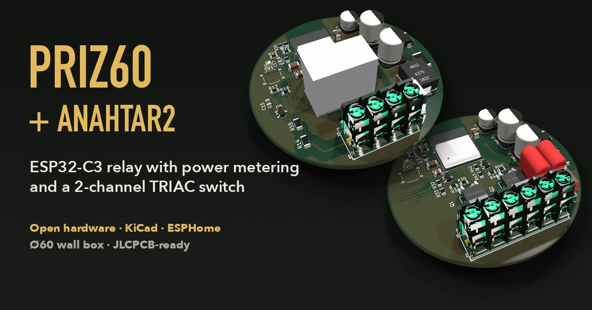
I designed two small boards to make the wall socket and the light switch smart, and the double switch also has a version without neutral. They all fit in a Ø60 wall box behind the socket or the switch, run on an ESP32-C3 and connect to Home Assistant through ESPHome. No cloud, no app.
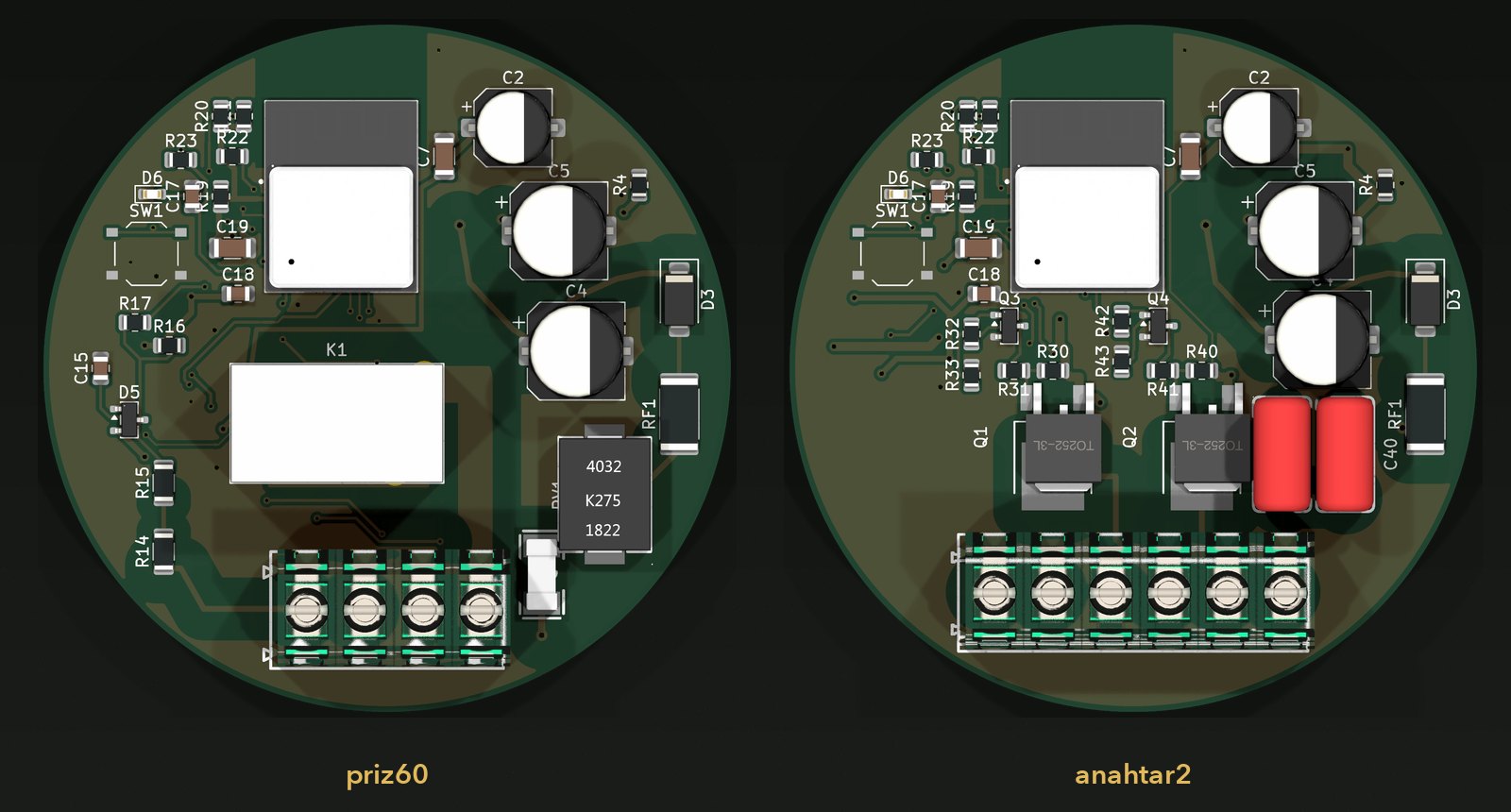
- priz60: a relay module. It switches the socket in front of it and measures current, voltage, power and energy.
- anahtar2: a two-channel light switch without relays. It drives the lamps with TRIACs, and the existing double wall switch stays in place.
- anahtar2l: the version of anahtar2 without neutral. It is for buildings with no neutral in the switch box; the board powers itself through the lamps.
The KiCad projects, Gerber/BOM/CPL files ready for JLCPCB and the ESPHome configurations are free to download at the end of the post.
Safety first
All of the boards are non-isolated. The circuit ground (GND) is tied to the mains, so every point on the board, the ESP included, sits at 230 V. That is the price of the small size and low cost: an isolated supply does not fit in a Ø60 box.
- Nothing gets connected to the board while it is on the mains: no USB-serial adapter, no scope probe, no computer. Programming is done through the test points (TP1-TP6) with the mains disconnected. Later updates come over Wi-Fi (OTA).
- The enclosure must be fully insulating. There is no connection to the outside (USB, sensors), and there must not be one.
- The circuit must be protected by a breaker and a 30 mA RCD.
- The boards have not been manufactured yet and no prototype has been tested. The numbers below come from simulation and calculation.
If you have no experience working with mains voltage, do not install these boards. The files are open for studying the design and for learning.
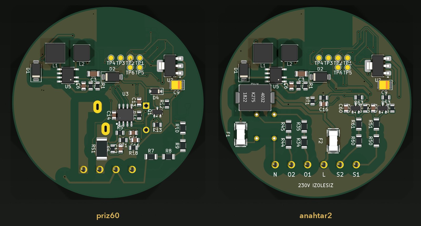
priz60: a relay with power metering
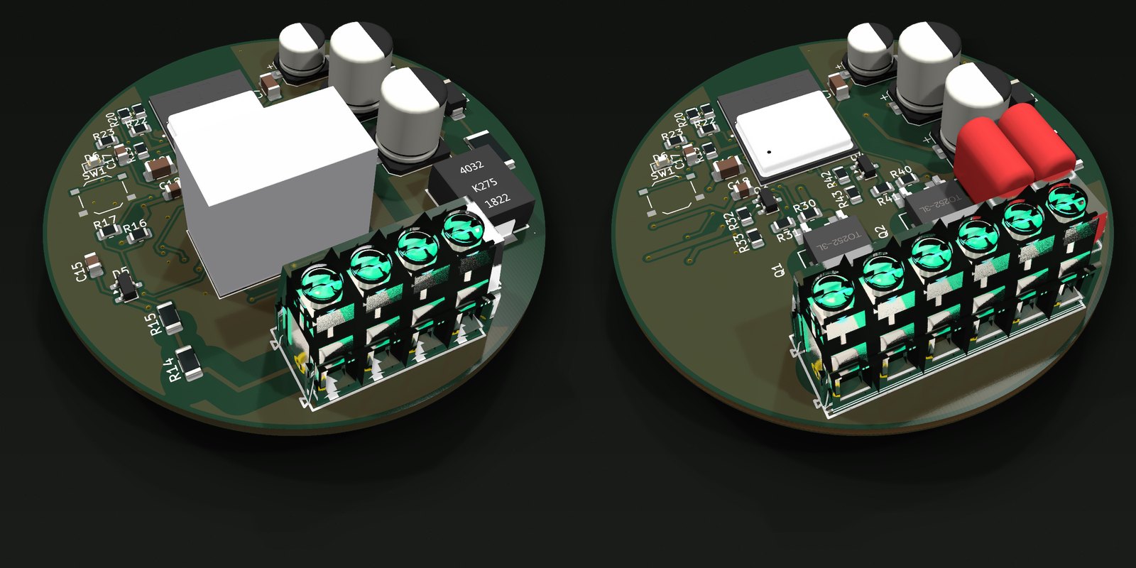
Terminal block (left to right): SW · N · L · O. L comes from the mains, O goes to the socket, N is needed for the supply, and the wall switch connects to SW.
L ── 1 mΩ shunt ── relay COM → NO ── O (socket)
N ── F1 500 mA T ── varistor ── 10 Ω ── M7 ── π filter (4.7µ / 1 mH / 4.7µ)
→ LNK306 buck → 5 V → AMS1117 → 3.3 V → ESP32-C3- Relay: Hongfa HF32FV-16 (16 A, 5 V coil). The coil pulls in at full voltage for 100 ms, then a 50% PWM at 20 kHz holds it. Coil power drops from 0.4 W to about 0.1 W, which matters in a closed wall box.
- Metering: BL0937. Current is measured across a 1 mΩ shunt, voltage through a 4 × 470k / 1k divider. ESPHome's
hlw8012component (model: BL0937) reads it directly. - Supply: a buck built around a Power Integrations LNK306. The board's GND is tied to L; the buck runs from N and produces +5 V relative to L.
- Wall switch input: SW → 2 × 100k (1206) → BAT54S clamp → GPIO. When the switch closes to L, the input goes LOW. Every flip of a classic switch toggles the relay.
How much current?
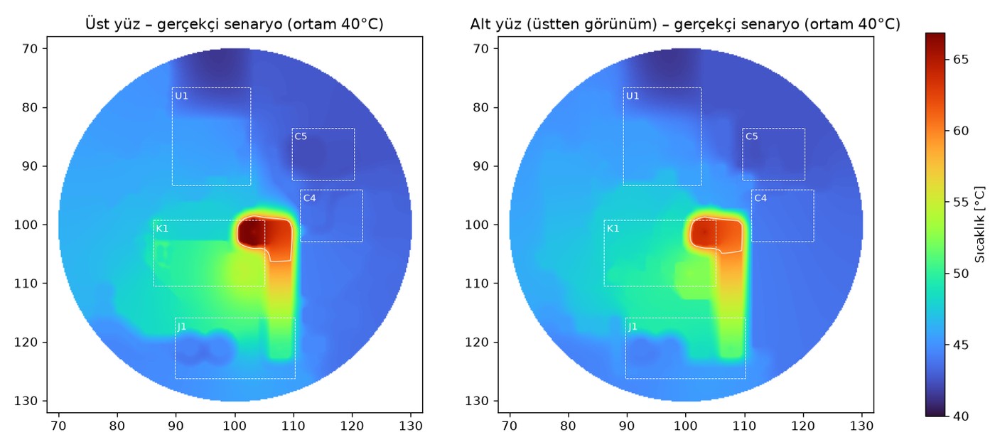
The relay is rated 16 A, but the board cannot carry that continuously. I estimated the current density and heating of the copper with a simple finite-difference model (40°C ambient, 2 oz copper, 3/5/8 mΩ scenarios for the relay contact). The hottest point is the relay's NO pin:
| Continuous current | Relay pin (realistic scenario) |
|---|---|
| 8 A | 57°C |
| 10 A | 67°C |
| 12 A | 78°C |
| 16 A | 108°C |
So the board is good for about 10 A continuous, with 16 A only for short periods. That is enough for a 2 kW heater or a washing machine, not for a 3.5 kW oven.
Protection in software
- If the current goes above 16 A, the relay is released.
- If the NTC on the board goes above 85°C, the relay is released and a thermal lockout engages. The lockout survives a power cut. While it is active, the relay cannot be switched on from the wall switch, the button or Home Assistant. The "Termal kilidi aç" (release thermal lockout) button in Home Assistant only releases it once the board is below 60°C.
anahtar2: a two-channel TRIAC switch
Terminal block: S1 · S2 · L · O1 · O2 · N. The double wall switch connects to S1 and S2 and stays where it is; the lamps are fed from O1 and O2. This version needs a neutral.
- Switching: one BT136S-600E TRIAC per channel (TO-252, 4 A / 600 V). Up to 100 W per lamp; at that load the TRIAC dissipates about 0.4 W. No relay means no click and no contact wear.
- Gate drive: ESP → AO3400A → 330 Ω → gate. The gate current is about 12 mA and negative (TRIAC quadrants II and III), so a single N-MOSFET is enough.
- Built-in bypass: on each output, O → 2 × 1k → 47 nF X2 → N. With the switch off, LED lamps glow or flicker from the small current that leaks through the TRIAC; the bypass gives that current another path. No separate bypass module is needed.
- Supply: the same parts as priz60, but here the LNK306 runs as a buck-boost with a negative output. L is the circuit's +5 V rail and the ESP's GND sits 5 V below L. Since the TRIAC's MT1 can connect straight to L, the gate drive stays simple.
- Protection: a 2 A T fuse in the L line, a 500 mA T fuse and a 275 VAC varistor on the supply. There is an NTC between the two TRIACs: above 95°C both lamps turn off and a thermal lockout engages, just like on priz60 (released below 70°C).
anahtar2l: the version without neutral
In older buildings the switch box often has no neutral: only the live wire and the wires to the lamps come into it. anahtar2l is for that case. Terminal block: S1 · S2 · L · O1 · O2 (the 6th position is unused). The idea is the same as the Shelly 1L/2L: the board powers itself through the lamps.
- Supply through the lamps: O1 and O2 are combined with two M7 diodes → 500 mA T fuse → 10 Ω → π filter → LNK306 buck-boost (-3.9 V relative to L) → 470 µF polymer capacitor → ME6211 LDO → 3.3 V. With a lamp off, the small current the board draws flows through the lamp.
- Supply window: when a lamp is on and its TRIAC conducts, there is no voltage left across the board. So with both lamps on, channel 1 fires 1.5 ms late in every positive half-cycle (
charge_delay), and the board feeds itself in that gap. With only one lamp on there is no delay; the path through the lamp that is off supplies the board. - Zero crossing: O1 → 2 × 470k → 10k → IO7, with a BAT54S clamp. To drive the gates in step with the zero crossing I wrote a component for ESPHome (
components/triac_nl). It runs every 50 µs on an ESP-IDF hardware timer and releases the gate 0.8 ms before each zero crossing so the TRIAC can turn off. If the zero crossing is lost, both channels turn off. - Pulsed gate: the gate is driven through 150 Ω at about 18 mA, but not continuously through the firing window: it gets a 100 µs pulse every 300 µs. If an LED driver lets the current drop below the TRIAC's holding current, the next pulse fires it again. The average gate current is about a third of continuous drive, which matters on a board powered through the lamps.
- Installation requirements: a bypass must be fitted next to each lamp (in the ceiling box), for example a Shelly Bypass or 47 nF X2 in series with 2 × 1k. Without it, LED lamps glow when off and the board's supply stays weak. At least one lamp must be fitted, and lamp 1 (O1) must always be fitted: the zero crossing comes from O1 only, and without lamp 1 neither channel can turn on. In a single-lamp installation, the lamp goes on O1. The "Sıfır geçiş" (zero crossing) diagnostic sensor in Home Assistant shows this state.
There is also a meerkat logo on the top side.
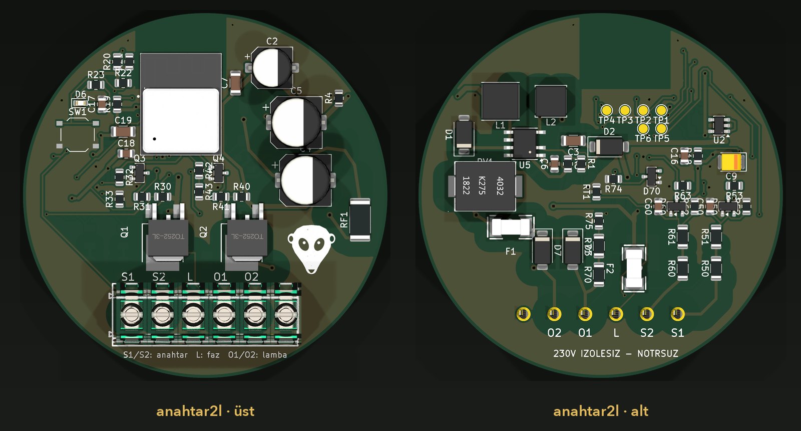
Board design
All three boards are 2-layer and Ø60 round. Being non-isolated, they have no classic "mains side / low-voltage side" split, but the different mains nodes still need spacing between them. I defined three net classes in KiCad's custom rules file (.kicad_dru):
| Class | Nets | Minimum clearance |
|---|---|---|
| HV | N, O, S, buck input | 2.5 mm |
| SWN | the LNK306 switching node | 2.0 mm |
| HVCH | intermediate nodes of series resistor chains | 1.5 mm |
Placement was done with Python scripts (scripts/place.py). The high-current paths and mains copper were drawn by script too (copper60.py, copper2t.py, copper2l.py), and my own autorouter, fastroute, connected the remaining signal traces. On priz60 and anahtar2l, a final step joins the GND copper islands on the top and bottom layers with vias. All three boards give 0 errors and 0 unconnected pads in KiCad DRC, and 0 errors in ERC.
Parts cost (JLCPCB, October 2026 prices, boards and assembly included): for priz60, 5 boards come to about $53 plus extended part fees (17 × $3); for anahtar2, 5 boards are $92, 10 boards $126 and 50 boards $385.
ESPHome
All three boards come with a ready YAML. Wi-Fi credentials go into secrets.yaml, and the first flash is done with the mains disconnected, through test points TP1-TP6 (3V3, GND, TXD, RXD, IO9, EN) with a USB-serial adapter:
uvx esphome run priz60.yamlIn Home Assistant, priz60 shows up as a relay switch plus current, voltage, power, energy and board temperature sensors; anahtar2 shows up as two lights, two wall switch inputs and a TRIAC temperature. Both have a "Termal kilit" (thermal lockout) status and a "Termal kilidi aç" button. On priz60, the BL0937 coefficients should be calibrated on first setup with a known load and a multimeter.
The anahtar2l YAML needs the components/triac_nl folder next to it (the package has both together). In Home Assistant it looks like anahtar2, plus a "Sıfır geçiş" (zero crossing) diagnostic sensor. charge_delay, zero_cross_offset and the gate pulse are set in the YAML.
To verify on the prototype
- The LNK306 supply: output voltage and ripple under load and with Wi-Fi on, and the SOURCE pin temperature. Measure only through an isolation transformer.
- EMI: whether the π filter is enough.
- priz60: thermal test with a thermocouple on the relay pins at 10 A and 16 A in a closed wall box; BL0937 calibration.
- anahtar2: glow when off and flicker when on with small LED lamps (3-5 W); TRIAC temperature with two 100 W loads; inrush current of LED drivers.
- anahtar2l: that the 3.9 V rail does not collapse with both lamps on and Wi-Fi running (raise
charge_delayif needed); measuring the zero-crossing delay with a scope and tuning it; that the TRIAC keeps conducting through every half-cycle with the pulsed gate on different LED lamps.
Download
| File | Contents | Size |
|---|---|---|
| priz60-kicad.zip | KiCad 10 project: schematic, PCB, rules, footprints and 3D models, schematic PDF, Gerber/BOM/CPL, ESPHome YAML, placement and copper scripts, thermal simulation | 3.5 MB |
| anahtar2-kicad.zip | KiCad 10 project: schematic, PCB, rules, footprints and 3D models, schematic PDF, Gerber/BOM/CPL, ESPHome YAML, scripts | 3.5 MB |
| priz60-gerber.zip | Gerber + Excellon only, ready to upload to JLCPCB | 0.1 MB |
| anahtar2-gerber.zip | Gerber + Excellon only, ready to upload to JLCPCB | 0.1 MB |
| anahtar2l-kicad.zip | KiCad 10 project: schematic, PCB, rules, footprints and 3D models, schematic PDF, Gerber/BOM/CPL, ESPHome YAML and the triac_nl component, scripts, logo | 4.2 MB |
| anahtar2l-gerber.zip | Gerber + Excellon only, ready to upload to JLCPCB | 0.1 MB |
| priz-anahtar-esphome.zip | ESPHome configuration for all three boards, the triac_nl component for anahtar2l and a setup note | 12 KB |
The JLCPCB BOM and CPL files are in the production/ folder of each KiCad package. Always check part orientation in the assembly preview: KiCad and JLCPCB define 0° differently for some packages.
The comments in the project files and the READMEs are in Turkish.